
Forza Motorsport 4
Forza 3 and my first shifter approach
In my previous post, I discussed my dissatisfaction with Forza Motorsport 3 and the SST Lightning shifter I modified to work with it.
I was always aware that my original circuit design was less clean than it could have been. For one, it required direct modification of the third party shifter … which is usually not pretty. Two, it used a lot of different IC's that probably could have been consolidated into the logic of a single microcontroller.
However, I was generally aware of the tradeoffs between the two and made the decision to go with a bunch of individual IC's consciously at the time. For one thing, I actually wanted to print a circuit board. Second, I decided it was more important to go through the motions of it as a learning experience rather than focusing on an optimal design. And, third, I could always take the microcontroller approach the next time.
Future goals for my next shifter
Find a better shifter
With the generally unintuitive behavior of the SST Lightning, my next shifter needed to be something that I wouldn't feel ashamed of putting in front of any normal stick shift capable driver.
Parse the USB output directly with an adapter
Creating a custom circuit board and modifying a shifter is far too difficult and complicated for most people, and it isn't first option that comes to mind when you think of ways to make a third party shifter compatible with your own steering wheel. The natural inclination is to just put an adapter of some sort between the wheel and the shifter, without modifying anything So that's what I wanted to build this time around.
The release of Forza Motorsport 4
The above thoughts percolated for many months while my sim racing cockpit sat idle. As Forza Motorsport 4 gradually approached its official release date of October 11th, 2011, I resolved to go fix my rig in preparation for the new game, even though the new game honestly didn't look all that different.
Finding the new shifter
It's hard to say how exactly I found it, but suffice it to say that, after occasional bouts of 30 minute Google search sessions, I ran across the TSW 6 speed shifter and some associated useful reviews. Check out the following features.
- Centered on gears 3/4
- Decent throw
- Reverse all the way on the left with extra resistance
- Gear below reverse locked out
I don't know how I managed to miss the existence of the TSW shifter in 2009, but it became quickly apparent that I had chosen the wrong shifter two years ago. This was what I needed.
OK, it was a bit expensive, but it wasn't going to be possible to build a shifter like this on my own right now. One criteria down.
Figuring out how to build the adapter
The platform – Arduino
The Arduino is a popular low cost and open source micro controller platform. The basic version of this can be picked up for around 30 dollars.
Luckily, I had an Arduino Duemlianove that had been sitting around in my apartment for a couple of years from a Sparkfun talk at Google. It's always strangely coincidental how you find a use for things that you could never have anticipated.
The USB Host Shield
Of course, just having an Arduino lying around doesn't do you much good. You need a way to physically connect to the USB shifter, and you need to be able to host it via software. Arduino's can be expended by the use of "shields", which are essentially just additional boards that can be stacked on top of the Arduino. With shields, you can add Ethernet ports, wireless modules, and all other kinds of expanded functionality to an Arduino.
Luckily for me, someone developed a USB Host Shield that stacks on the Arduino and provides you one standard size USB host port to interface with USB devices.
With the Arduino and USB Host Shield, it looked like I would have everything I needed to build my adapter. Second and last criteria met.
Putting it all together (The old way)
The TSW shifter was the first part to arrive. My Arduino project was going to take a lot more time to come together, so, in the mean time, I decided to figure out if I could hack up a way for the TSW shifter to work with my SST Lightning adapter.
It turns out that not only is the TSW shifter nicer in build quality than the SST lightning, it's also better for modding too. The switches are wired via ribbon cable to a controller PCB mounted on the outside of the shifter. This means to access the switches, all you really need to do is pop the ribbon cable off the PCB and stick header pins into the ribbon cable.
The only difficulty here is that the TSW shifter operates active high (All switches are 0V by default, and the active one is 5V) instead of active low (default 5V, active 0V) like the SST Lightning. So to make the shifter work with my SST Lightning circuit, I needed to invert the switch values before passing them in. I built a simple circuit to do this.
I placed the inverter circuit between the TSW shifter and my SST lightning circuit … and it worked as expected in the game. I was actually quite pleased with how well the TSW shifter played in the game. I now knew that the TSW shifter was going to work one way or the other, and that I could spend some additional effort and time on the Arduino approach while having a working TSW shifter in game.
Putting it altogether (The new way)
First milestone: Do anything with the Arduino. That wasn't too hard at all. I just downloaded the Arduino Development Kit for Windows, plugged the Arduino into my USB port, and I got an LED to blink on the Arduino. Success!
Second milestone: Finding a way to interface with the joystick. This was the trickiest part. I attached the USB Host Shield to the Arduino, and then attached the shifter to the USB host shield.
The makers of the USB Host Shield have supporting code for it that is on version 2. Unfortunately, the USBJoystick code I found on the net was meant to work with version 1. I spent a couple of days messing with porting over the code for the USBJoystick to v2 before I realized it would take too long to understand how everything worked.
Eventually, I gave up on the port and just compiled the old USB Host Shield (v1) code on the Arduino along with the sample USBJoystick code to see if it would work. Debug outputs started popping out of the serial monitor with every shift. Success!
Third milestone: Output analog voltages from the Arduino to the Fanatec wheel.
Now, the tricky part about micro controllers like the Arduino is that they don't output analog voltages. They generally either out
put either 5V or 0V. Being microcontrollers, however, they can do this switching very often and very quickly. In order to get an analog voltage, what you need to do to get, say, 3V, out of the Arduino, is output 5V 60% of the time (3V being 60% of 5V, of course), and use a low pass filter to smooth things out.What are the implications of doing this? Well, you need to select an appropriate resistor and capacitor that creates good low pass filter characteristics for your intended application. And your actual output has some deviations from a true analog voltage output that you need to be aware of.
Ripple – Because the microprocessor behind the scenes is constantly flipping its voltage from 5V to 0V and back again, the actual output from your low pass filter will never settle at an exact value. Instead, it will bounce around your target voltage value. Allow too much ripple in your filter output, and you could end up sending unexpecting values or voltages downstream that you never really intended.
Settling time – The time it will take for your filter output arrive within some acceptable range of your target output is now non-trivial. For dimming Christmas lights, this probably isn't a big deal, but for gaming, you can imagine that it actually matters a bit.
Ripple and settling time are at odds with each others. You can reduce the ripple in your filter output, but at the expense of the settling time when the desired output changes. That's why knowing your application needs is important. Turns out that there's a really good calculator for displaying the results of a low pass filter for PWM in Japan. I used the heck out of this and it came in very handy, as you'll see next.
Fourth milestone: Reduce the latency of the switching as much as possible
Of course, in gaming, it's important that controllers be as responsive as possible. One of the advantages of my old circuit was that the response time would have been nearly instantaneous. Now, with my new adapter, there would be a slight lag time in polling the USB outputs, plus a settling time required by the low pass filter. Instantaneous was no longer in the cards.
In order to reduce the latency, the first thing I did was up the polling frequency in the software for the Arduino. It was defaulting to 50 ms in the USBJoystick code, which was way too long. I changed it to every 1 ms. This seemed to work (although the real polling frequency was more like every 2 ms due to actual code execution). Anyway, no ill effects, and that chopped a good 48 ms off the latency of any shift.
The second piece of this was to select a decent looking low pass filter.
I'm not going to break this down tremendously, but the default PWM frequency out of the Arduino is about 1 kHz, so in order to minimize latency and keep ripple within reasonable levels, I selected a 4.7k resistor and a 1uF capacitor. This produces a transient analysis that looks like the following.
As you can see, it arrives at the 90% mark in around 10 ms. I could have improved the latency more by testing the exact limits of the ripple (I was very conservative on this for obvious reasons), or by modifying the Arduino timers to switch its PWM outputs faster. This turned out to be more of a pain in the ass than I had hoped, so I ended up skipping it and taking the 10ms hit (which isn't that much anyway).
Fifth milestone: Make it look reasonably nice
This is where the Arduino Protoshield comes in. It's basically an Arduino shield with a prototyping area where you can put your own stuff.
Anyway, there's not much to say here. The low pass filters and the outputs of this filters into the Fanatec wheel have to go somewhere, so they go here. I also added a mini DIN breakout board for the 6 pin connector (that interfaces to the Fanatec wheel). With the right combination of resistors, capacitors, etc … you end up with something like the below.

Finale
Here's the final product.
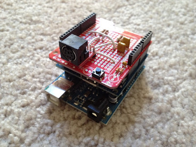
- It's powered by any USB port.
- It interfaces directly with an unmodified TSW 6-speed shifter (and powers it as well).
- It has a standard 6 pin mini-DIN port (aka PS/2 port) that can be connected directly to a Fanatec wheel.
- The top shield is my custom output shield to the Fanatec, with the low pass filters going to the 6 pin mini-DIN port for the Fanatec, the middle shield is the USB Host Shield, and the bottom is the Arduino.
It would be nice to put it inside a custom enclosure of some sort, but I think that's going to be unlikely unless I can find a 3D printer to work with (and learn how to use it). Anyway, it's pretty sturdy as is … and perhaps more interestingly, much easier to replicate off the shelf by others.
Finally, here's a YouTube video that puts this all together – http://www.youtube.com/watch?v=2utk_62blmM.
Hope you enjoyed the walkthrough!
